
In conclusion, not much to say about my method of taking things apart, gathering in-depth knowledge of them, and doing little experiments.Īlthough I love making new things, I cannot always come up with sensible builds because my inherent habit keeps me busy constantly learning about new things. So go that way only if you are willing to accept a few minor compromises! Also note at this point that you can use the 5VDC available from the M5Stack Atom Lite to power this relay unit instead of using an external power supply, but this will degrade the galvanic isolation somewhat. Thus, the transistor has to be able to handle the requisite 70mA for the relay coil happily when 9mA is applied to its base (take my maths with a grain of salt and verify it by yourself if you plan to try this design in any way).Ĭlick to access SRD-05VDC-SL-C-Datasheet.pdfĪlthough I did not take photos or videos for proof, I can tell you that the first tests were very pleasant.
#CONTROL HIGH VOLTAGE DEVICES ARDUINO RELAY TUTORIAL SERIES#
The optocoupler driving circuit delivers circa 18mA to the light sender inside the optocoupler using a 120Ω series resistor (R4), which equates to about 9mA of output current for the specified least favourable current-transfer ratio of 50%.

A red visual indicator (LED1) is wired in parallel with the relay coil as well, with a 1KΩ series resistor (R3).

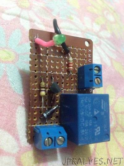
Now the S8050 transistor (Q1) routes the externally supplied +5VDC through the relay coil (K1) when a signal from the optocoupler is received at the base of the transistor.Īs you can see, an additional 100uF/16V polarized capacitor (C1) is used across the relay coil as a tricky buffer. This design uses a common PC817 optocoupler (OC1) to isolate the sensitive microcontroller I/O port from any potential power spikes.


 0 kommentar(er)
